
Auto Parts Search

Learn how to repair a car or truck, install or remove parts, wire an engine, reset warning lights, replace fuel filter, fix auto body and more.
Get Automotix DIY!
 Automotix DIY provides automotive consumers and do it yourselfers; the most comprehensive repair information about 1989 Chevrolet Beretta car and truck
repair procedures including Chevrolet engine diagrams, wiring diagrams, repair work estimating measures, technical service bulletins, auto body work
guidance, starter & alternator replacement procedures, serpentine belt replacement procedures, radiator & hose replacement procedures, tune-up &
drivability specifications, quick lube illustrations, preventive maintenance guide, engine light reset instructions, parts removal and install
procedures, fuel filter replacement directions, component location diagrams, air filter locations & replacement instructions, a/c
system specifications, and general auto service procedures. You don't have to be a car mechanic or technician to know how to fix
your 1989 Chevrolet Beretta automobile. Try the Automotix DIY solution today!
Automotix DIY provides automotive consumers and do it yourselfers; the most comprehensive repair information about 1989 Chevrolet Beretta car and truck
repair procedures including Chevrolet engine diagrams, wiring diagrams, repair work estimating measures, technical service bulletins, auto body work
guidance, starter & alternator replacement procedures, serpentine belt replacement procedures, radiator & hose replacement procedures, tune-up &
drivability specifications, quick lube illustrations, preventive maintenance guide, engine light reset instructions, parts removal and install
procedures, fuel filter replacement directions, component location diagrams, air filter locations & replacement instructions, a/c
system specifications, and general auto service procedures. You don't have to be a car mechanic or technician to know how to fix
your 1989 Chevrolet Beretta automobile. Try the Automotix DIY solution today!
DIY REPAIR SAMPLES > CONTINUE EXPLORING >
We have info for following modifications of 1989 Chevrolet Beretta
- 1989 Chevrolet Beretta 2.8 V6 GAS, CID:173, Fuel Injection, Aspiration:173, Engine VIN:, Desg:W
- 1989 Chevrolet Beretta 2.0 L4 GAS, CID:122, Fuel Injection, Aspiration:122, Engine VIN:, Desg:1
- 1989 Chevrolet Beretta GT 2.8 V6 GAS, CID:173, Fuel Injection, Aspiration:173, Engine VIN:, Desg:W
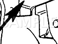
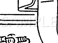
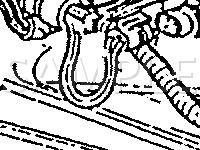
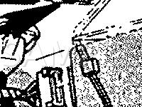
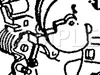
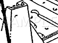
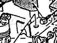
COMPONENT LOCATION DIAGRAMS FOR 1989 Chevrolet Beretta AUTOMOBILES
Component location diagrams for most 1989 Chevrolet Beretta cars and light trucks sold in the U.S. from 1990+.
 Cruise Control Clutch Switch Diagram for 1989 Chevrolet Beretta 2.0 L4 GAS Cruise Control Clutch Switch Diagram for 1989 Chevrolet Beretta 2.0 L4 GASComponents on diagram: |
 Clutch Start Switch Diagram for 1989 Chevrolet Beretta 2.8 V6 GAS Clutch Start Switch Diagram for 1989 Chevrolet Beretta 2.8 V6 GASComponents on diagram: |
 Transaxle Position Switch Diagram for 1989 Chevrolet Beretta GT 2.8 V6 GAS Transaxle Position Switch Diagram for 1989 Chevrolet Beretta GT 2.8 V6 GASComponents on diagram: |
 Electronic Control Module Diagram for 1989 Chevrolet Beretta GT 2.8 V6 GAS Electronic Control Module Diagram for 1989 Chevrolet Beretta GT 2.8 V6 GASComponents on diagram: |
 Coolant Temperature Sender/Switch Diagram for 1989 Chevrolet Beretta 2.0 L4 GAS Coolant Temperature Sender/Switch Diagram for 1989 Chevrolet Beretta 2.0 L4 GASComponents on diagram: |
 Outside Air Temperature Sensor Diagram for 1989 Chevrolet Beretta GT 2.8 V6 GAS Outside Air Temperature Sensor Diagram for 1989 Chevrolet Beretta GT 2.8 V6 GASComponents on diagram: |
 Fog Light Relay Diagram for 1989 Chevrolet Beretta 2.0 L4 GAS Fog Light Relay Diagram for 1989 Chevrolet Beretta 2.0 L4 GASComponents on diagram: |
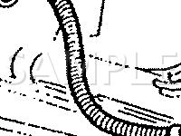 Crankshaft Position Sensor Diagram for 1989 Chevrolet Beretta 2.8 V6 GAS Crankshaft Position Sensor Diagram for 1989 Chevrolet Beretta 2.8 V6 GASComponents on diagram: |
 Manifold Absolute Pressure Sensor Diagram for 1989 Chevrolet Beretta GT 2.8 V6 GAS Manifold Absolute Pressure Sensor Diagram for 1989 Chevrolet Beretta GT 2.8 V6 GASComponents on diagram: |
 Idle Air Control Valve Diagram for 1989 Chevrolet Beretta 2.0 L4 GAS Idle Air Control Valve Diagram for 1989 Chevrolet Beretta 2.0 L4 GASComponents on diagram: |
CLICK HERE TO GET FULL ACCESS TO 1989 Chevrolet Beretta PARTS/COMPONENTS LOCATION DIAGRAMS!
Shop online for auto body parts, engines, wheels, lights...
| More parts |
Auto Repair Quick Search
Help me find
Search DIY repair manuals by VIN...
| Get the Complete Technical Service Bulletins! |
 Access diagrams and repair information such as wiring diagrams,
diagnosis and repair charts, manufacturer
service bulletins, and OEM Part
numbers of your 1989 Chevrolet Beretta vehicle. Access diagrams and repair information such as wiring diagrams,
diagnosis and repair charts, manufacturer
service bulletins, and OEM Part
numbers of your 1989 Chevrolet Beretta vehicle.
|
| Access the Complete guide! |
Need To Fix Your Car or Truck?
Try Our Repair Service Finder
Auto Repair Quick Search
Help me find
